10 Best Flanged Heaters for Industrial Applications
Industrial heating systems depend on more than raw power. They need steady heat transfer, compatible materials, and dependable controls. A Flanged Heater can serve tanks, pressure vessels, and process lines where equipment requires a securely mounted heating element. The right choice can support consistent operation. The wrong one may cause uneven heating, premature wear, or avoidable downtime.
This guide introduces ten flanged heaters for industrial applications and the details worth checking before selection. We consider factors such as heater capacity, sheath material, flange dimensions, operating temperature, process medium, and control options. Manufacturer specifications matter, but they do not tell the whole story. Installation conditions and maintenance access matter, too. Small details count.
No single model fits every plant. A heater suitable for clean water may not suit a corrosive fluid or a high-temperature process. That distinction is easy to miss. The options in this list should be compared against actual operating requirements, not just price or headline wattage. Check pressure and temperature limits, electrical supply, and material compatibility in the product documentation. Where specifications are unclear, ask the manufacturer or a qualified engineer before ordering. This is not the most exciting part of buying equipment, but it can prevent a costly mismatch. Use the recommendations as a practical starting point, then verify each model for your application.
What Flanged Heaters Are and How They Work
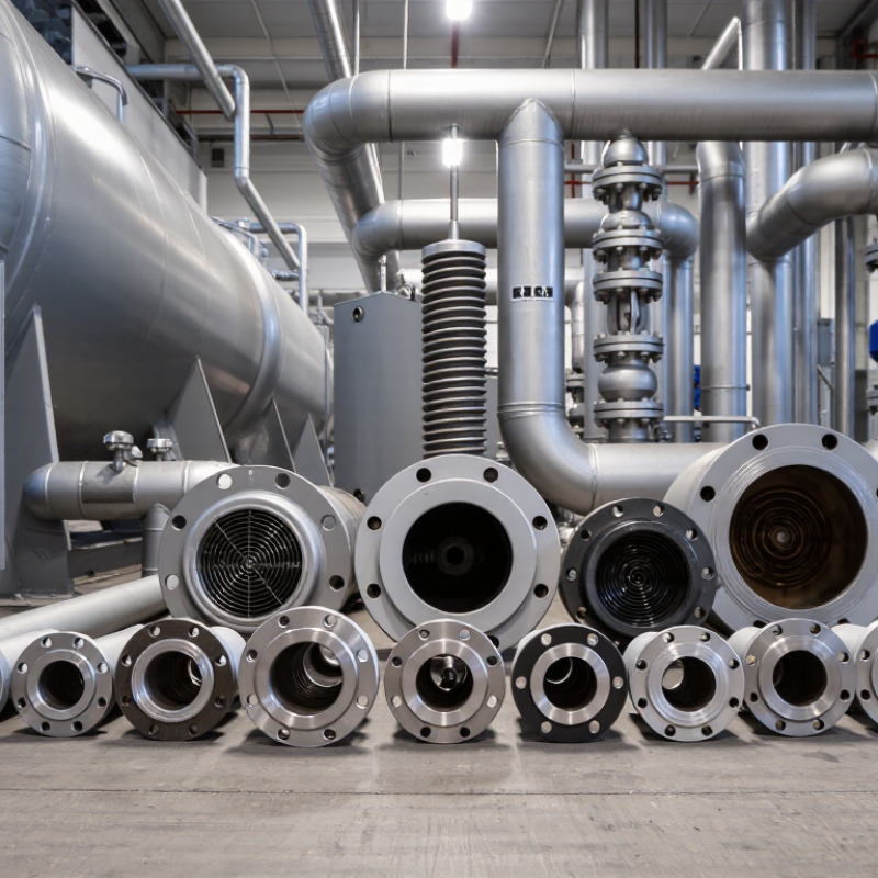
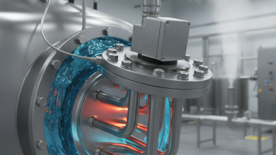
A flanged heater is an electric immersion heater mounted through a bolted flange on a tank or vessel. Its heating elements extend into the liquid, while the flange seals and supports the assembly. Inside each element, electrical resistance wire generates heat; a compacted insulating material transfers that heat to a metal sheath. The sheath then warms the surrounding liquid. Simple in principle. Not effortless in practice.
The U.S. Department of Energy’s Improving Process Heating System Performance: A Sourcebook for Industry estimates that process heating uses about two-thirds of industrial energy. That broad figure covers many technologies, not flanged heaters alone, but it shows why heat transfer and control matter. In a vessel, liquid level, flow, temperature, and fluid properties affect element performance. Poor circulation can create hot spots, while deposits may insulate the sheath and raise its temperature. These details are easy to overlook.
A practical selection starts with the medium, required heat-up time, operating temperature, and available electrical supply. Engineers also check flange dimensions, element watt density, sheath compatibility, and over-temperature protection. For example, a viscous fluid may need lower surface loading or improved circulation. No single configuration suits every tank. Even well-sized equipment can underperform when fouling or changing process conditions go unchecked. DOE’s energy figures describe the larger process-heating challenge; they do not replace application-specific calculations or operating measurements.
10 Best Flanged Heaters for Industrial Applications – What Flanged Heaters Are and How They Work
A flanged heater is an electric immersion heater whose tubular heating elements are mounted to a flange that bolts to a vessel or pipe nozzle. The elements transfer heat directly to the surrounding liquid or gas. The configurations below are application-oriented examples, not specific products; final materials, power, and watt density must be selected for the process conditions.
| No. | Configuration | Typical application | Common element sheath options | Watt-density approach | Key selection considerations |
|---|---|---|---|---|---|
| 1 | General-purpose water heater | Process water, storage tanks, and water-based systems | Copper or stainless steel, selected for water chemistry and temperature | Moderate; scale-forming water may require a lower loading | Consider mineral content, scale buildup, immersion level, and over-temperature protection. |
| 2 | Low-contamination water heater | Deionized or high-purity water service | Typically stainless steel; grade depends on water quality and operating conditions | Low to moderate, determined by flow and temperature limits | Verify that sheath and wetted flange materials are compatible with the water and purity requirements. |
| 3 | Light-oil heater | Heating low-viscosity oils in process tanks and equipment | Carbon steel or alloy sheath, subject to oil chemistry and temperature | Generally lower than for water to limit film temperature and oil degradation | Check oil viscosity at startup, circulation, allowable film temperature, and thermal safeguards. |
| 4 | Heavy-oil or viscous-fluid heater | Viscous oils and other fluids that heat slowly or circulate poorly | Material selected for the fluid; corrosion-resistant alloys may be required | Low, with element layout designed to support heat transfer | Assess cold-start viscosity, local stagnation, circulation, and the possibility of deposits or coking. |
| 5 | Heat-transfer-fluid heater | Closed-loop thermal-fluid systems and process circulation loops | Alloy sheath chosen for the fluid and its maximum operating temperature | Typically conservative; confirm the fluid supplier's film-temperature limits | Provide adequate flow across the elements and use controls to prevent overheating during low-flow conditions. |
| 6 | Corrosive-liquid heater | Acidic, alkaline, or salt-bearing process solutions | A compatible alloy or other suitable wetted material; selection is chemistry-specific | Often low to moderate, depending on chemistry and heat-transfer conditions | Confirm concentration, contaminants, temperature, and compatibility of every wetted component; no single alloy suits all corrosive fluids. |
| 7 | High-pressure vessel heater | Pressurized process vessels and pressure-rated circulation systems | Selected for process compatibility and the specified pressure and temperature design | Set from the fluid, flow, and allowable element-surface temperature | The flange, gasket, vessel connection, and heater assembly must meet applicable pressure-design requirements. |
| 8 | Finned gas or air heater | Ducts, gas streams, and equipment requiring heated air | Heat-resistant alloy tubing; fin material and construction depend on temperature and environment | Designed around gas velocity and heat transfer; gas service often needs extended surface area | Check airflow, element temperature, pressure drop, clearances, and protection against operation without adequate flow. |
| 9 | Hygienic-process heater | Food, beverage, or other processes with defined cleanability requirements | Suitable stainless steel or other approved wetted material, specified for the process | Selected to limit fouling and meet process temperature and cleaning requirements | Specify surface finish, drainability, seals, and any required hygienic design or regulatory criteria. |
| 10 | Circulation-loop heater | Pumped liquid systems where flow passes across the heating elements | Chosen to match the circulating fluid and operating conditions | Based on verified flow rate, fluid properties, and required temperature rise | Include flow or low-level interlocks as appropriate, temperature controls, and safe shutdown provisions. |
Selection note: “Best” depends on the fluid or gas, operating pressure and temperature, required heat-up time, available power, vessel geometry, and applicable codes. Confirm the design with a qualified heater or process engineer; sheath materials and watt density should not be selected from application labels alone.
Related Posts
-
China Top Flanged Heater Manufacturers Suppliers?
-
China Top Flange Heating Manufacturers for Global Buyers
-
What Are the Benefits of Using Flanged Heaters in Industry?
-

Top 10 Flanged Heaters to Explore at 2026 Canton Fair?
-
2026 Top Flanged Heater Trends for Global Buyers?
-
Top Flanged Heater Benefits for Global Buyers?
-

Phone
-

E-mail
-

Whatsapp
Whatsapp