
What Is an Airduct Heater and How Does It Work?
An Airduct Heater is an electric heating device installed inside an air distribution system. It warms moving air before that air reaches rooms, work areas, or controlled spaces. Unlike a portable heater, it works as part of the building’s ventilation or HVAC design. The idea is simple. Metal heating elements receive electrical power and produce heat. A fan then pushes air across those elements and through the ductwork.
In practice, performance depends on more than the heater’s rated output. Airflow, duct size, temperature settings, insulation, and electrical capacity all affect results. A technician may check airflow with measuring instruments and inspect wiring, terminals, controls, and safety switches. Many systems include high-limit protection, which interrupts power if internal temperatures rise too far. That distinction matters. A heater that seems powerful may still perform poorly when airflow is restricted.
This guide explains the main components of an Airduct Heater and follows the path of heat through a typical system. It also considers installation choices, energy use, maintenance, and common operating problems. Reliable guidance should come from manufacturer instructions, recognized HVAC practices, and qualified professionals. Local requirements can vary, so assumptions deserve careful review. Small errors matter. For example, a dirty filter can reduce airflow, increase element temperature, and trigger protective shutdowns. No design is perfect, either. Even a correctly selected heater may need adjustment when occupancy, weather, or ventilation demand changes. Understanding these details helps readers evaluate performance realistically and make safer decisions.
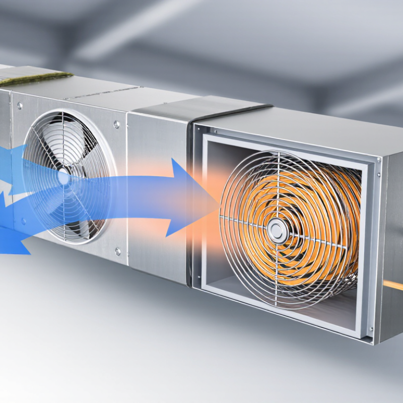
What Is an Air Duct Heater? Ratings and UL 1995 Requirements
What Is an Air Duct Heater? Ratings and UL 1995 Requirements
An air duct heater is an electric resistance assembly installed inside a supply or terminal duct. Its elements warm moving air after a thermostat or control signal calls for heat. The heater’s rating normally lists kilowatts, voltage, phase, airflow, and maximum temperature rise. A 10 kW heater does not deliver the same result in every system. Air volume matters. ASHRAE’s HVAC Systems and Equipment Handbook uses the relationship Q = 1.08 × CFM × ΔT for sensible air heating, helping engineers match capacity with airflow.
Energy control deserves attention. The U.S. Energy Information Administration’s 2018 Commercial Buildings Energy Consumption Survey reported that space heating represented about 32% of commercial building site energy use. Correct sizing can reduce unnecessary cycling and overheating. A practical check includes measuring supply airflow, voltage, static pressure, and discharge temperature. The grille should feel warm, not sharply hot. Small details matter.
UL 1995 evaluates heating and cooling equipment for electrical safety, grounding, insulation, wiring, spacing, enclosure protection, and abnormal operating conditions. It also addresses safeguards against excessive temperatures and fire-related hazards. A UL 1995 listing supports confidence in the manufactured assembly, but it does not approve poor field installation. Controls should prevent heater operation when airflow is lost, where the design requires that protection. A clean rating label can still mislead if technicians overlook phase compatibility or minimum airflow. That mistake remains common. Engineering judgment is still necessary.
What Is an Airduct Heater and How Does It Work? - What Is an Air Duct Heater? Ratings and UL 1995 Requirements
| Data Dimension | Typical Information | How It Applies |
|---|---|---|
| Definition | An air duct heater is an electric heating assembly installed inside, beside, or downstream of an air-handling duct. | It raises the temperature of moving air for space heating, supplemental heat, ventilation tempering, or freeze protection. |
| Primary Heating Method | Electrical resistance heating converts electrical energy into heat through resistance elements. | The elements transfer heat directly to the air as the blower moves air across their heated surfaces. |
| Main Components | Heating elements, frame or casing, electrical terminals, contactors or relays, airflow controls, temperature controls, and safety limit devices. | The components work together to produce heat, regulate capacity, and disconnect power during unsafe operating conditions. |
| Common Installation Locations | Supply-air ducts, air-handling units, rooftop units, ventilation systems, and terminal heating sections. | The heater should be installed where airflow is sufficiently uniform and where service access and required clearances are available. |
| Typical Electrical Supply | Common system voltages include 120 V, 208 V, 240 V, 277 V, and 480 V AC, depending on the application. | The heater voltage must match the available electrical supply and the equipment nameplate requirements. |
| Typical Heating Capacity | Duct-heater capacities vary widely, from small supplemental-heating sections to large multi-stage assemblies rated in tens or hundreds of kilowatts. | Capacity is selected from the required airflow, entering-air temperature, desired leaving-air temperature, voltage, and available electrical service. |
| Basic Heating Formula | For electric resistance heat, input power is approximately equal to the sum of energized element wattages. | A simplified air-temperature calculation uses: Q = 1.08 × CFM × ΔT, where Q is sensible heat in BTU/h and ΔT is the air-temperature rise in °F. |
| Airflow Requirement | The required airflow depends on heater capacity and the permitted temperature rise. | Insufficient airflow can cause excessive element temperature, nuisance trips, equipment damage, or a fire hazard. |
| Capacity Control | Heating output may be controlled in stages or by proportional electronic control. | Staged control energizes selected element groups, while proportional control adjusts output more continuously to maintain the target temperature. |
| Airflow-Proving Protection | A pressure switch, airflow switch, fan interlock, or equivalent control can prevent heating when airflow is not proven. | The protection helps stop the elements from operating with a failed, stopped, or incorrectly operating supply fan. |
| High-Limit Protection | Automatic-reset and manual-reset temperature limit devices are commonly used. | These devices interrupt heater operation if the internal temperature becomes excessive because of low airflow, blocked ducts, or control failure. |
| Electrical Current | For a single-phase resistive load, current is approximately I = P ÷ V. For a balanced three-phase load, current is approximately I = P ÷ (√3 × V). | Actual circuit sizing must also account for applicable electrical codes, conductor temperature ratings, overcurrent protection, and continuous-load requirements. |
| Pressure Drop | The heater assembly adds resistance to airflow; the exact pressure drop depends on face velocity, element geometry, casing design, and heater size. | Fan selection and system balancing should include the heater’s published pressure-drop data. |
| UL 1995 Scope | UL 1995 is a safety standard for heating and cooling equipment, including applicable electrical heating equipment used in HVAC systems. | Equipment evaluated to this standard is assessed for construction, electrical safety, temperature-related hazards, operation, and other applicable requirements. |
| UL 1995 Construction Considerations | Relevant evaluations can include enclosure construction, insulation, spacing, grounding, component suitability, wiring, terminals, and protection against electric shock. | The final design must be evaluated as a complete assembly according to the applicable edition and certification conditions. |
| UL 1995 Operating Safety | Safety evaluation addresses abnormal conditions, overheating risks, dielectric strength, leakage current, grounding continuity, and control performance as applicable. | Compliance does not replace correct installation, commissioning, maintenance, or compliance with local electrical and mechanical codes. |
| Required Nameplate Information | Typical information includes rated voltage, phase, frequency, heating capacity or current, wiring details, and installation limitations. | The nameplate provides the baseline data needed for electrical connection, equipment selection, and service work. |
| Efficiency | Electric resistance heating converts nearly all input electrical energy into heat at the point of use. | Overall system performance still depends on fan energy, duct losses, controls, insulation, and the source of electricity. |
| Maintenance Checks | Inspect wiring and terminals, clean accumulated dust, verify airflow, test safety controls, and check for loose or damaged elements. | Maintenance should be performed with power isolated and by qualified personnel in accordance with the installation instructions and applicable codes. |
Related Posts
-
China Best Air Duct Heater Manufacturer and Supplier?
-
How to Choose the Best Airduct Heater for Your Needs?
-
How to Choose the Right Bitumen Heater for Your Needs?
-
Top Tips for Choosing the Best Hot Oil Heater?
-
Top 5 Air Fin Heater Models You Should Consider?
-

How to Choose the Right Heater Element for Your Needs?
-

Phone
-

E-mail
-

Whatsapp
Whatsapp