What Is a Pipeline Inlet and How Does It Work?
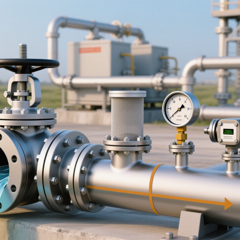
A pipeline inlet is the point where fluid enters a pipeline, processing unit, or station. Its exact meaning depends on the system: a gas transmission station inlet differs from a refinery process inlet. Still, each inlet must guide flow safely into equipment and provide operators with useful information. Typical components may include an isolation valve, strainer or filter, pressure instruments, and a flow meter. The layout depends on the fluid, operating pressure, and design requirements. The term can be slippery.
The scale makes inlet design consequential. The U.S. Energy Information Administration describes a natural gas network spanning roughly three million miles of pipelines. At this scale, a blocked strainer, faulty reading, or poorly managed pressure change can affect operations beyond one connection. The International Energy Agency’s Global Methane Tracker 2024 also estimates that fossil fuel operations produced about 120 million tonnes of methane emissions in 2023. That figure covers the wider sector, not pipeline inlets alone, but it underscores why leak detection and sound operating practices matter.
This guide explains what a Pipeline Inlet does, how fluid moves through its components, and what operators monitor. It also distinguishes inlet equipment from nearby pipeline and process equipment, which are sometimes confused. Small errors travel. Actual configurations vary with service conditions and engineering standards, so a general overview cannot replace site-specific design documents or qualified inspection.
What a Pipeline Inlet Is
A pipeline inlet is the designated point where a fluid enters a pipeline, process unit, or section of a larger network. It may be a simple connection, such as a flanged pipe end, or a compact assembly with valves and instruments. The exact meaning depends on the system drawing; the term can be less precise than it sounds. In a water transfer line, for example, the inlet may be where water passes from a storage tank into the pipe. It is not necessarily the pipeline’s first point geographically.
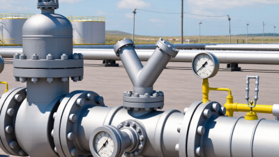
An inlet assembly often includes an isolation valve, a pressure gauge, and sometimes a strainer or flow meter. These parts help operators control entry, check operating conditions, and limit debris reaching downstream equipment. When flow begins, fluid crosses the inlet boundary and moves through the pipe under a pressure difference created by pumps, gravity, or the upstream system. A technician might check for leaks around the flange and compare the pressure reading with the expected operating range. Small details matter. A partly closed valve can restrict flow, while a blocked strainer can cause pressure to drop. The inlet’s purpose is straightforward, but its design and exact limits should be confirmed from the system documentation.
What Is a Pipeline Inlet and How Does It Work?
The inlet is the opening where fluid enters a pipeline. Its size influences the fluid’s velocity: for the same flow rate, a larger pipe diameter means a lower average velocity.
Illustrative calculation for a constant flow rate of 0.01 m³/s through circular inlets. Velocities are calculated from Q = vA, where Q is flow rate and A is the pipe’s cross-sectional area.
Main Components of a Pipeline Inlet
A pipeline inlet is the point where fluid enters a pipeline system or a processing facility. Its components help control flow, remove unwanted debris, and provide useful operating information. The exact arrangement depends on the fluid, pressure, and facility design. In practice, the layout is rarely as tidy as a diagram suggests.
A typical inlet includes an isolation valve, which lets trained personnel stop flow during maintenance or an emergency. A strainer or filter can catch particles before they reach sensitive equipment, though not every inlet needs one. Pressure and temperature instruments show changing conditions, while a flow meter may track incoming volume. Some systems also use a control valve to adjust flow. Small parts matter. Drains, vents, and sturdy pipe supports can make inspection and maintenance more manageable. Their placement should follow the approved design, not guesswork.
Tips: Check that instrument readings are plausible, and look for signs of leaks or unusual vibration during routine inspections. Never assume a clogged strainer is the only cause of low flow. Follow site procedures and involve qualified personnel before changing valves or opening equipment. A clear label helps, too.
How Material Enters the Pipeline
A pipeline inlet is the controlled point where material enters a pipe network. The material may arrive from a storage tank, treatment unit, well, or another line. At a water facility, for example, it might pass through a short intake pipe before reaching a pump. Small details matter. A valve regulates entry, while a strainer can catch debris that might obstruct downstream equipment. The setup depends on the material and the system’s design, so an inlet that works well for clean water may not suit a thick liquid or a gas.
Material moves into the pipeline when pressure at the source exceeds pressure inside the line. Pumps can provide that push, but gravity may be enough in some layouts. Operators use pressure gauges and flow meters to check whether the inlet is behaving as expected. If pressure drops suddenly, a blocked screen or partly closed valve could be the cause. Readings are useful, but they do not explain every problem on their own. A meter may drift, and a small leak can be difficult to spot. Regular inspection helps catch issues before they affect flow farther along the pipeline.
How Inlet Conditions Shape Flow
What Is a Pipeline Inlet and How Does It Work?
How Inlet Conditions Shape Flow
A pipeline inlet is where fluid enters a pipe, pump, or process system. Its conditions affect how smoothly that fluid moves downstream. Pressure, temperature, viscosity, and flow speed all matter. So does the shape of the incoming flow. An elbow close to the inlet can send fluid in uneven streams, while a sudden reducer can speed it up.
Small details matter. In liquid lines, a sharp pressure drop may bring pressure near the fluid’s vapor pressure, raising the risk of cavitation. Gas flow responds differently as pressure and density change.
Imagine water entering a pump after passing through a tight bend. The flow may reach the impeller unevenly, causing noise, vibration, or unstable performance. A straight approach can help, but the required length depends on the equipment and piping layout.
It is easy to focus only on pipe diameter; that misses the inlet profile. Not always obvious. Engineers check pressure and temperature at operating conditions, review nearby fittings, and compare readings with equipment guidance. A pressure gauge alone cannot reveal every swirl or velocity imbalance. Measurements and careful inspection together give a clearer picture of what the inlet is doing.
Safety and Control at the Inlet
A pipeline inlet is the point where fluid enters a pipeline system. Its safety role begins before flow travels downstream. Inlet equipment may include an isolation valve, pressure gauges, filters, and a control valve. Together, these components help manage incoming pressure and catch debris that could damage equipment. Small changes matter. A sudden pressure rise can strain pipework, while a blocked filter may reduce flow. Operators use instrument readings and operating procedures to spot these changes early, rather than relying on a single gauge.
The exact setup depends on the fluid, pipeline design, and operating conditions. Isolation valves let trained personnel separate equipment for inspection or maintenance. Pressure controls help keep conditions within the system’s specified limits. Filters also need regular checks; a filter that looks intact may still be clogged. In practice, inlet readings are not always tidy, and instruments can drift or respond slowly. That uncertainty deserves attention. Maintenance records, calibrated instruments, and clear alarm procedures support safer decisions, but no inlet arrangement is foolproof. It must be reviewed against real operating data and changed when conditions warrant.