What Is a Pipeline Inlet and How Does It Work?

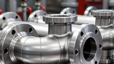
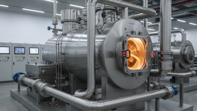
A Pipeline Inlet is the point where fluid enters a pipeline, processing facility, or equipment train. Its exact design depends on the service: natural gas, water, and liquid hydrocarbons require different safeguards. A typical inlet may include an isolation valve, filter or strainer, pressure and temperature instruments, and a flow-control device. Look closely at a gas installation, and you may see a filter vessel catching debris before it reaches sensitive equipment. Small details matter.

The scale makes reliable inlet design important. The U.S. Energy Information Administration describes a natural-gas pipeline network spanning more than three million miles, linking production areas, storage, and customers (EIA, “Natural Gas Pipelines”). That figure is U.S.-specific, not a global total. PHMSA’s pipeline performance reporting also tracks system mileage and incidents, giving operators and regulators a basis for monitoring safety trends. These sources do not define one universal inlet arrangement; operating pressure, fluid properties, and site conditions shape the equipment.

In operation, fluid crosses the inlet boundary, passes through screening or separation where needed, and is measured and regulated before moving downstream. Instruments help operators spot pressure changes, while valves can isolate equipment for inspection or maintenance. Not complicated in principle. Yet an inlet is not merely a pipe opening: poor filtration, incorrect sizing, or unclear readings can affect the whole system. The practical question is what the inlet must protect, measure, and control in its specific application. EIA and PHMSA data provide useful context, but engineering decisions still require project-specific design and qualified review.
What Is a Pipeline Inlet and How Does It Work?

Define a Pipeline Inlet: The Entry Point from Source to Pipeline System

A pipeline inlet is the point where fluid leaves a source and enters a pipeline system.

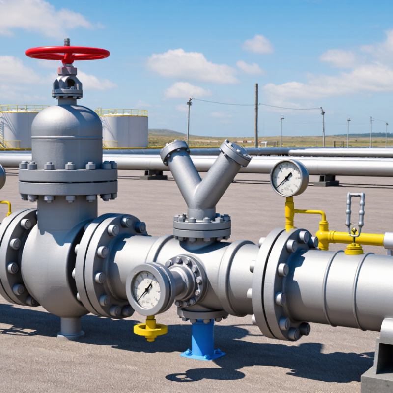
The source may be a storage tank, treatment unit, wellhead, or process vessel. At this boundary, an inlet assembly directs flow into the line and provides a place to measure or control it. It may include an isolation valve, pressure gauge, flow meter, strainer, or reducer. The exact components depend on the fluid and operating conditions. For example, a liquid line may use a strainer to catch debris before it reaches a pump. A gas inlet may require pressure control and careful sealing. Small details matter.

During operation, a pressure difference moves fluid from the source into the pipeline. Valves regulate or stop flow, while instruments show whether pressure and flow rate stay within design limits. An undersized inlet can restrict flow and increase pressure loss. Poor support can let vibration stress nearby joints. A neat drawing can make the design look simpler than it is. Engineers also consider temperature changes, startup surges, maintenance access, and possible contaminants. Those checks can be easy to miss during a quick site review. For instance, a pressure tap placed too close to a bend may produce an unsteady reading.

Identify Inlet Equipment: Valves, Strainers, Meters, and Pressure Controls

At a pipeline inlet, equipment protects downstream measurement and control points. A shutoff valve isolates the line for maintenance. A strainer catches rust, weld slag, or scale before debris reaches meters and control valves. A differential-pressure gauge across the strainer can reveal a growing blockage. The meter measures flow, while a regulator or control valve maintains the required downstream pressure. Small details matter.

The U.S. Department of Energy’s Improving Pumping System Performance sourcebook reports that pumping systems can account for 25–50% of energy use in some industrial facilities. That figure is not specific to pipeline inlets, but it shows why avoidable pressure loss deserves attention where pumps must compensate. An oversized strainer may seem safer, yet poor sizing or neglected cleaning can still cause trouble. A tidy diagram does not guarantee a tidy installation.

Tips: Check pressure on both sides of the strainer during routine inspections. Confirm meter readings against operating conditions. Record valve settings after adjustments; memory is unreliable.

Trace the Flow: How Pressure and Flow Move Through the Inlet

A pipeline inlet is the point where fluid enters a line or process unit. Its role is more than providing an opening. Upstream pressure pushes liquid or gas toward a lower-pressure area, creating flow. The inlet’s size and shape affect how evenly that flow develops. A sudden contraction can accelerate fluid and create turbulence. That costs pressure. Small details matter.

Operators compare pressure readings before and after the inlet, ideally at similar flow rates. A larger-than-usual pressure difference may indicate a clogged screen, buildup, or partly closed valve. A flow meter adds another clue: pressure alone cannot show how much fluid is moving. During startup, opening a valve gradually can limit surges that shake supports or stress seals. The response also depends on temperature, viscosity, pipe diameter, and downstream demand. It is easy to assume one gauge tells the whole story. It doesn’t. Readings may lag, and one measurement point can miss uneven flow. Instrument placement and pressure trends offer a clearer picture, though no setup is perfect. A slight needle flutter during startup may be harmless; repeated spikes deserve a closer inspection.

What Is a Pipeline Inlet and How Does It Work?

Trace the flow: how pressure and velocity change through a pipeline inlet.

This illustrative steady-flow example shows gauge pressure falling as the inlet narrows and flow velocity rises. As the passage widens, velocity decreases and some pressure recovers. In steady incompressible flow, the volumetric flow rate is approximately constant along the pipe; actual values depend on the fluid, geometry, and operating conditions.

Screen Erosion Velocity: API RP 14E Uses Vₑ = C/√ρₘ (ft/s, lb/ft³)

At a pipeline inlet, a screen slows debris only by redirecting flow through its open area. That creates local jets. API RP 14E gives a useful reference for erosional velocity: Ve = C / √ρm, where Ve is in ft/s and mixture density, ρm, is in lb/ft³. The coefficient C is empirical, so it must be chosen for the service and unit convention. It is not a universal material constant.

The equation estimates a velocity limit for flowing production fluids; it does not directly predict screen life. A screen’s openings can experience higher local velocities than the average velocity in the inlet pipe, especially when debris blocks part of the mesh. For example, a partly blinded screen may send flow through a few clear openings, creating narrow, fast jets that wear edges or nearby metal. The distinction matters.

Use the calculated value as a screening check, not a guarantee against erosion. Review fluid composition, solids, corrosion potential, flow rate, screen geometry, and operating changes. A density estimate alone can hide important variation in multiphase flow. Field inspection can reveal wear patterns that the equation cannot. That gap deserves attention.

Review Inlet Safeguards: Isolation, Pressure Relief, and Leak Detection

A pipeline inlet is the controlled entry point where fluid moves from upstream equipment into a line. Its fittings and instruments help operators manage incoming flow and pressure. The exact arrangement depends on the fluid, operating conditions, and pipeline design. Small details matter.

Isolation safeguards let staff stop flow during maintenance or an upset. A closed valve can separate the inlet from downstream sections, but only if its position is confirmed and the valve seals properly. Pressure gauges show changing conditions near the connection. Relief devices can protect equipment when pressure rises beyond its specified limit, directing excess fluid to a designed safe destination. They need suitable settings and regular inspection; a relief device is not a substitute for sound operating controls.

Leak detection combines instruments with attentive field checks. Operators may compare inlet and outlet flow, review pressure trends, and investigate unexpected changes. A damp patch, unusual odor, or steady hiss near a joint deserves prompt assessment. Sensors can give early warning, yet coverage and response times vary. No safeguard is perfect. Weather, sensor drift, or a missed valve check can complicate a clear reading, so records and careful follow-up remain essential.

What Is a Pipeline Inlet and How Does It Work?

Review of common inlet safeguards for isolation, pressure relief, and leak detection

Inlet Component or Safeguard Purpose Typical Location How It Works Inspection or Verification
Pipeline inlet Receives fluid from an upstream pipeline and directs it into a facility or downstream process system. At the point where the incoming pipeline connects to a processing, storage, or distribution facility. Flow normally passes through inlet piping and associated valves, measurement instruments, and—where required—filters or separators. Confirm the flow path, equipment identification, operating limits, and connection integrity against current facility documentation.
Manual isolation valve Allows operators to isolate the inlet for maintenance, emergencies, or controlled shutdowns. On the inlet line, commonly near the facility boundary or another designated isolation point. A valve is moved between open and closed positions to stop or permit flow. Its suitability depends on the service, pressure, materials, and operating conditions. Check accessibility, position indication, operability, leakage, and maintenance records under the applicable inspection program.
Emergency shutdown valve (ESDV) Provides remotely or automatically initiated isolation when a defined hazardous condition occurs. At a facility inlet or other location selected by the facility’s hazard and operability assessment. A shutdown signal can drive the valve to its designated safe position. The logic, power source, and fail position are established by the system design. Function-test the valve and its shutdown logic at the intervals specified by the safety instrumented system and maintenance procedures.
Pressure relief device Protects equipment from pressure exceeding its design or allowable operating limits. On protected equipment or piping where pressure can be trapped or rise above the permitted limit. A relief valve or other suitable device opens, vents, or diverts fluid when its set conditions are reached. Discharge routing must account for the fluid and associated hazards. Verify device suitability, set-pressure documentation, discharge-path condition, and inspection or testing status.
Pressure monitoring and alarms Helps operators identify abnormal pressure, including conditions that may indicate blockage, equipment malfunction, or an upset. At selected inlet points and protected equipment, based on the process design. Transmitters or gauges measure pressure. Alarm limits and any automatic actions are set according to the operating envelope and risk assessment. Check instrument calibration, alarm function, and consistency between readings and approved operating procedures.
Leak detection Identifies loss of containment so operators or automated systems can investigate and respond. May include sensors near potential release points, along the pipeline, or within a control system monitoring flow and pressure. Detection methods can include gas or liquid sensors, pressure or flow imbalance monitoring, and operator observation. No single method detects every leak scenario. Test sensors and alarms as specified; review monitoring coverage, communications, response procedures, and any unexplained flow or pressure deviations.
Check valve (where required) Helps limit reverse flow that could affect upstream equipment or create an unsafe operating condition. In the inlet line where the process design identifies a need to control reverse flow. It closes in response to reverse flow or a change in differential pressure. Performance depends on valve type and operating conditions. Inspect and test according to the service and maintenance plan; confirm that the valve does not obstruct required flow or isolation functions.
Inlet filtration or separation (where required) Removes or collects solids, liquids, or other contaminants that could damage downstream equipment or affect process performance. Downstream of the inlet connection and upstream of equipment requiring cleaner or conditioned flow. A filter, strainer, or separator retains or removes material from the incoming stream. Differential-pressure monitoring may indicate loading or blockage. Inspect drains and internals as appropriate, monitor differential pressure, and follow safe isolation and depressurization procedures before opening equipment.

Note: Safeguard selection, location, set points, test intervals, and shutdown actions are site-specific. They should be based on applicable regulations, engineering design, process hazards, and approved operating procedures.