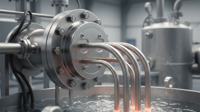
Inline Heating is becoming a practical choice for industrial systems that require controlled, responsive, and space-efficient temperature management. It places the heating element directly within the process line. This design transfers energy close to the moving fluid, reducing unnecessary heat loss through external surfaces. It can support faster warm-up times, steadier outlet temperatures, and more consistent product quality.
Control matters.
Dr. Frank P. Incropera, a respected heat-transfer author, describes the principle clearly: “Heat transfer is the transport of energy resulting from a temperature difference.” Inline Heating applies this principle inside the process path. Properly selected systems can heat water, oils, chemicals, and other compatible fluids with accurate sensor feedback. Engineers can also reduce bulky tanks, long pipe runs, and complicated secondary circuits. These gains may improve floor-space use and simplify maintenance access.
However, Inline Heating is not automatically the best answer. Flow rate, viscosity, pressure, material compatibility, and maximum temperature must be evaluated carefully. A compact heater may perform poorly when scaling, air pockets, or unstable flow are ignored. That is an easy mistake. Experience shows that reliable performance depends on sizing, instrumentation, insulation, and planned cleaning. Energy savings also require measurement, not assumptions. A well-designed system should protect the fluid, the equipment, and the operators. It should also allow safe shutdown when abnormal conditions appear. The strongest case for Inline Heating comes from matching the technology to the process, rather than treating it as a universal solution.
Why Choose Inline Heating for Industrial Applications?
What Is Inline Heating in Industrial Applications?
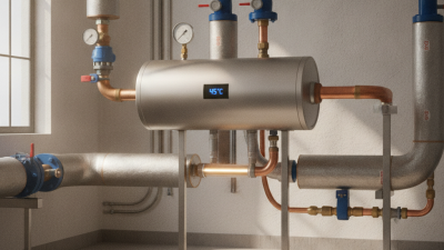
Inline heating warms a liquid or gas while it moves through a pipe, hose, or process vessel. Electrical elements transfer heat directly into the flowing medium. Sensors then adjust output to maintain a target temperature. This differs from batch heating, where material waits inside a tank.
The approach suits water, oils, chemicals, compressed air, and other controlled process streams. It can reduce floor space, shorten heat-up time, and limit heat loss around storage tanks. The International Energy Agency reports that industry used about 37% of global final energy in 2022. The U.S. Department of Energy also estimates process heating represents roughly half of industrial energy use in American manufacturing. These figures make precise heat delivery worth examining. However, inline heating is not automatically efficient. Poor insulation, oversized heaters, and unstable flow can waste energy.
Tips: Measure flow rate, inlet temperature, outlet temperature, and pressure drop before selecting equipment. Add insulation around hot pipework. Use independent temperature protection for safety. Review readings during start-up, not only during steady operation.
In practice, a food-processing line may need gentle, even heating. A chemical line may need rapid response and corrosion-resistant materials. Engineers should check viscosity changes, cleaning procedures, and sensor placement. One overlooked detail can distort the control signal. I have seen designs focus on heater capacity while ignoring flow variation. That is an uncomfortable, but useful, design lesson. Reliable performance depends on the whole system, not the heater alone.
Inline heating transfers heat directly to a continuously flowing liquid, enabling fast temperature control without requiring a large storage tank.
Calculation basis: water heated from 20°C to 80°C with a specific heat capacity of 4.186 kJ/kg·°C, assuming 1 L of water ≈ 1 kg and no heat loss. Actual system power should include efficiency and heat-loss allowances.
Why Choose Inline Heating for Industrial Applications?
How Inline Heating Systems Operate
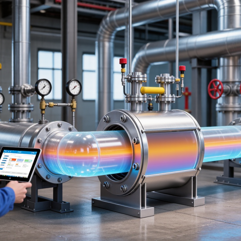
Inline heating systems warm liquids or gases as they move through a process line. The medium enters a heated chamber, passes over electric elements, and leaves at a controlled temperature. Sensors measure outlet conditions continuously. A controller then adjusts power through proportional, integral, and derivative logic. Flow switches can cut power when movement stops, reducing overheating risks.
This design avoids heating a large storage tank. It can also shorten startup time and reduce heat loss around idle equipment. The U.S. Department of Energy reports that process heating represents about 51% of onsite energy use in American manufacturing. The International Energy Agency estimates that industry consumes roughly 37% of global final energy. These figures explain why precise heat delivery matters. Still, efficiency claims need plant-level testing. Fouling, poor insulation, and unstable flow can change the result.
Tips: Match heater capacity to flow rate, pressure, and target temperature. Place sensors near the actual outlet. Test the system during cold starts and low-flow conditions. A clean pipe is not always a clean process.
In practice, operators should review temperature trends rather than trust one reading. A small delay may create uneven heating across the line. That detail is easy to miss. Periodic calibration, documented alarms, and thermal inspections support reliable operation. DOE process-heating guidance also recommends recovering usable heat where practical, although recovery layouts can add complexity. Less equipment is not always better.
| System Element | How It Operates | Typical Industrial Data | Operational Benefit | Common Applications |
|---|---|---|---|---|
| Process Fluid Inlet | A pump or pressure differential moves the liquid or gas into a heater installed directly in the process line. | Flow may be measured in L/min, m³/h, kg/h, or Nm³/h, depending on the medium and process. | Heating occurs only when material is required, reducing the need for a continuously heated storage vessel. | Water treatment, chemical dosing, compressed gases, fuel conditioning, and process utilities. |
| Heating Element or Heat Exchanger | Electrical resistance elements transfer heat directly to the flowing medium. Steam or thermal-fluid systems transfer heat indirectly through a heat-transfer surface. | Electrical heaters commonly use 230–480 V industrial power supplies; heat duty is calculated from mass flow, specific heat, temperature rise, and heat losses. | The heat source can be matched closely to the required duty, supporting compact equipment layouts. | Heating water, air, nitrogen, oils, cleaning fluids, and compatible chemical streams. |
| Temperature Sensor | An RTD, thermocouple, or other sensor measures the outlet or process temperature and sends feedback to the controller. | Platinum RTDs are widely used for stable measurement in moderate temperature ranges; thermocouples are suitable for broader and higher-temperature service. | Feedback control helps maintain the target temperature despite changes in flow rate or inlet temperature. | Batch transfer lines, continuous production lines, gas preheating, and hygienic fluid processing. |
| Control System | A temperature controller adjusts heater output using on/off, proportional, or PID control. PID control continuously corrects output based on temperature error and process response. | Control accuracy depends on sensor selection, installation, tuning, flow stability, and thermal design; the specified tolerance must be verified for each process. | Improves repeatability and helps prevent overheating, underheating, and unnecessary energy consumption. | Food and beverage processing, laboratory utilities, chemical production, and equipment protection. |
| Flow Monitoring | A flow switch, flowmeter, or differential-pressure device confirms that the medium is moving through the heater. | Minimum flow is established from heater watt density, fluid properties, allowable temperature rise, and equipment geometry. | Interlocking the heater with proven flow helps reduce the risk of localized overheating and element damage. | Pumped liquids, compressed-air systems, gas lines, circulation loops, and skid-mounted equipment. |
| Inline Housing and Connections | The heater is installed between upstream and downstream piping using threaded, flanged, sanitary, or other process connections selected for the service. | Pressure and temperature ratings are determined by the housing material, connection design, gasket selection, and applicable piping requirements. | A direct-piping arrangement can reduce footprint, intermediate handling, and heat loss between equipment stages. | Process skids, production lines, utility modules, and point-of-use heating stations. |
| Thermal Insulation | Insulation surrounds the heater body and adjacent hot piping to limit heat transfer to the surrounding environment. | Heat loss varies with surface temperature, insulation thickness, ambient conditions, airflow, and exposed surface area. | Reduces energy loss, protects personnel from hot surfaces, and supports more stable outlet temperatures. | High-temperature process lines, outdoor installations, hot-water systems, and thermal-fluid circuits. |
| Safety Protection | High-limit cutouts, over-temperature alarms, pressure protection, grounding, and emergency shutdown circuits remove power or isolate the process when unsafe conditions occur. | Protection settings must be coordinated with the heater rating, process pressure, fluid hazards, and applicable electrical and mechanical codes. | Provides an additional barrier against dry operation, excessive temperature, overpressure, and electrical faults. | Flammable-area installations, pressure systems, chemical service, and automated production equipment. |
| Outlet Temperature and Process Control | The heated medium exits at the controlled target temperature and proceeds directly to the next process stage. | The required heat duty can be estimated using Q = ṁ × Cp × ΔT, with additional allowance for heat loss and startup conditions. | Fast response and point-of-use heating can support continuous operation and reduce residence time in heated equipment. | Viscosity reduction, freeze protection, drying air, thermal conditioning, and temperature-sensitive manufacturing steps. |
Inline heating is gaining attention in industrial applications because it delivers heat where the process needs it. Its key advantage is direct, controlled energy delivery. Instead of warming a large vessel, heaters raise the fluid temperature as it moves. This can shorten thermal response time, reduce idle losses, and simplify temperature control. The U.S. Department of Energy’s Industrial Decarbonization Roadmap identifies industry as responsible for about 24% of U.S. greenhouse-gas emissions. Every avoided watt matters. In practical operations, stable outlet temperatures can protect coatings, improve viscosity control, and reduce material scrap. Small details matter.
Inline systems also require less floor space. They fit near pumps, manifolds, and process lines, reducing long heated runs. The International Energy Agency reports that industry consumes roughly 37% of global final energy. That scale demands closer attention to heat loss, insulation, and control accuracy. Modern sensors can adjust power quickly, but results depend on flow rate, fouling, and calibration. A heater sized only for average demand may underperform during cold starts. That is an easy mistake. Engineers should verify residence time, pressure drop, material compatibility, and maintenance access before installation. Inline heating is not automatically efficient. Poor tuning can create hot spots, while weak insulation wastes recovered heat. Real operating data should guide the final design, not catalog ratings alone.
Inline heating places controlled heat directly inside a flowing process line. It supports stable outlet temperatures, compact layouts, and faster response than many external heating methods. This matters because the International Energy Agency’s Energy Efficiency 2023 report identifies industry as using about 37% of global final energy. The U.S. Department of Energy also estimates that process heating represents nearly 60% of manufacturing energy use. Small efficiency gains can therefore influence operating costs.
Water and water-glycol mixtures are suitable for moderate-temperature heating and respond quickly to electrical control. Thermal oils suit higher temperatures, but viscosity increases during cold starts. They may need preheating and stronger circulation. Air and inert gases can also pass through inline heaters, provided flow is stable and materials resist oxidation. Clean, low-viscosity liquids are usually easier to manage. Syrups, resins, and slurries require careful velocity control because stagnant zones can create scorching or fouling.
Fluid compatibility deserves equal attention. Corrosive liquids may require specialized alloys, seals, and protective monitoring. Conductivity is less important for indirect element heaters than viscosity, flow rate, pressure, and chemical compatibility. Commissioning teams often discover that a correctly sized heater still performs poorly when sensors sit too far downstream. That detail is easy to miss. Design reviews should follow IEC 60519-1 principles, include low-flow protection, and verify actual fluid properties at operating temperature. The remaining uncertainty is unavoidable: laboratory viscosity data may not match a real production line after aging, contamination, or seasonal changes.
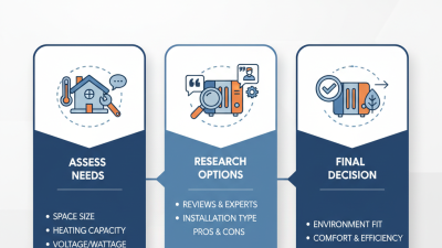
Selecting an inline heater requires more than matching a wattage to a process line. Start with the fluid’s flow rate, viscosity, inlet temperature, and target outlet temperature. These values determine the required thermal duty and help prevent unstable heating. A heater that is too small may run continuously, while an oversized unit can create hot spots or waste energy.
Pressure drop also deserves careful attention. Confirm that the heater will not restrict pumps, valves, or downstream equipment. Material compatibility matters when fluids are corrosive, abrasive, or sensitive to contamination. Stainless construction may suit many systems, but it is not automatically the best choice. Consider pressure ratings, operating temperature, insulation, and the surrounding environment. Control quality is equally important. Sensors should measure the process accurately, and adjustable control should respond to changing flow conditions. In practice, the first estimate is rarely perfect. Field measurements often reveal heat loss through pipes, fittings, and uninsulated surfaces.
Tips: Ask for the complete operating range, not only normal conditions. Check startup, shutdown, low-flow, and cleaning cycles. Include over-temperature protection and flow interlocks. Leave enough access for inspection and element replacement. Small details matter. A short trial under real conditions can expose problems that calculations miss, especially when flow fluctuates or the fluid changes seasonally. Reliable selection comes from comparing calculations with operating experience.